Notes on waveguides
I mainly follow Pozar’s book
Waveguides
A waveguide is one or more prismatic conductors used to transfer power in the form of time-varying electromagnetic fields.
- A transmission line is indeed a waveguide (with two conductors).
Different wave modes can propagate in a waveguide, depending on the frequency and the propagation characteristics (dependent on the geometry and the materials used).
- Transverse Electric (TE) and Transverse Magnetic (TM) modes have some component of the fields longitudinal with the waveguide
- Tranverse ElectroMagnetic (TEM) modes have purely transversal fields; these modes only exist in waveguides with two or more conductors.
Field model
Again, I use $\exp (-j\omega t)$ in the expansion rather than $\exp (+j\omega t)$
For a waveguide along $z$ we write the complex electric and magnetic fields of the forward wave at angular frequency $\omega$ as:
\(\bm E = (E_x(x,y)\bm 1_x + E_y(x,y)\bm 1_y + E_z(x,y)\bm 1_z) \exp (-j\omega t + jkz - \alpha z)\) \(\bm H = (H_x(x,y)\bm 1_x + H_y(x,y)\bm 1_y + H_z(x,y)\bm 1_z) \exp (-j\omega t + jkz - \alpha z)\)
- The real fields can be found taking the real part of the complex fields
- $\gamma = jk -\alpha$ is the (geometry- and material-dependent) propagation constant
- In the following we take $\alpha = 0$ for simplicity
TEM waves
Imposing $E_z=0$, $H_z=0$ and entering with these expressions into the sourceless Maxwell equations, \(\nabla\times\bm E = j\omega \mu H,\) \(\nabla\times\bm H = -j\omega \varepsilon E,\) we find that for a non-trivial solution we need: $k^2 = \omega^2\mu\varepsilon$.
- The wavenumber in the TEM mode is that of a free wave of angular frequency $\omega$ in a medium with $\mu$, $\varepsilon$
We also find that the traverse electric and magnetic fields $E_x\bm 1_x +E_y\bm 1_y$ and $H_x\bm 1_x + H_y\bm 1_y$ are solenoidal and irrotational.
- At the surface of a perfect conductor only normal electric fields and tangential magnetic fields are allowed.
- The transverse electric field derives from a potential that satisfies Laplace’s equation. \(E_x\bm 1_x +E_y\bm 1_y = - \nabla_t \phi; \quad \nabla^2_t \phi = 0\)
- TEM modes are only supported in waveguides with more than one conductor (else, $\phi=\mathrm{const}$ everywhere and the fields are zero). A waveguide with two conductors supports only wone TEM mode.
- The voltage between two conductors in the waveguide is $V = \int_2^1 \bm E\cdot \mathrm{d}\bm\ell =\phi_2-\phi_1$.
- The current through a conductor is $I = \oint \bm H \cdot \mathrm{d}\bm \ell$
The wave impedance of the TEM modes, i.e. the ratio between electric and magnetic fields at each point, is: \(Z_{TEM} = \frac{E}{H} = \sqrt{\frac{\mu}{\varepsilon}}\)
- Coincides with the wave impedance of a plane wave in a homogeneous medium with $\mu$, $\varepsilon$ (a.k.a. intrinsic impedance)
- This should not be confused with the characteristic impedance $Z_0$ of a transmission line, which is the ratio of voltage to current on the wires, nor any of the other impedances defined later
- $Z_0$ can be computed from $V$ and $I$ with the formulas above
- All the transmission line theory is TEM mode theory
TE waves
We now take $E_z=0$ but $H_z\neq 0$. After some algebra, the sourceless Maxwell equations yield the transverse fields $E_x$, $E_y$, $H_x$ and $H_y$ as a function of the transverse derivatives of $H_z$ and the square of the cutoff wavenumber, \(k_c^2 = \omega^2 \mu \varepsilon - k^2\)
- $H_z$ obeys a non-homogeneous Laplace equation (Helmholtz equation) with $k_c$ as “eigenvalue”
- Applying the boundary conditions fixes the value of $k_c$ for each possible eigensolution of the equation.
- We can also define the cutoff angular frequency as $\omega_c = k_c/\sqrt{\mu\varepsilon}$.
- Therefore, $k_c$ and $\omega_c$ for each TE mode depend on the geometry and materials
- Then, $k = \sqrt{\omega^2 \mu \varepsilon - k_c^2}$, and propagating TE modes exist only if $k$ is real. Else, the mode is evanescent
- TE modes are supported by any waveguide (regardless of the number of conductors)
- Note that coaxial cables can also support these modes, above a quite high frequency. These modes are usually undesired in coaxial cables
- The wave impedance of the TE mode is:
- The phase velocity $v_p = \omega/k$ is greater than $c_1$, the speed of light in the material. However, the group velocity $v_g = \partial\omega/\partial k$ is always $\leq c_1$ (and this is the relevant velocity for the propagation of signals)
TM waves
The same as TE waves, but we now take $E_z\neq 0$ but $H_z=0$. The same applies (although boundary conditions for the electric and magnetic fields on a perfect conductor are different, and thus the resulting cutoffs are also different)
- The wave impedance of the TM mode is:
Network analysis
Two-conductor TEM lines have well-defined voltage, current, characteristic impedance. This is not so in single-conductor waveguides.
For each TE and for each TM mode, we can define equivalent voltages and currents (a pair for the forward wave and another for the backward wave), following these guidelines
- $V$ and $I$ should be somehow proportional to the transverse electric field and magnetic field, respectively
- Their product should give the power flow
- The ratio $V/I$ is the characteristic impedance. Usually we select $V$ and $I$ so that this impedance matches the wave impedance. Alternatively, we make it equal to one (choice of “normalized impedances”)
Multiport networks
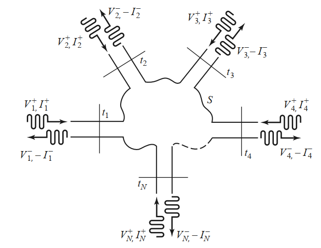
We can treat any microwave component as a black box with $N$ ports. We want to figure out the (linear) relation between any incident wave on one port and the outgoing wave through all ports (including the one)
- Each port represents a single mode in a waveguide or a transmission line
- If multiple modes exist on a waveguide, treat each as a separate port
- In general, all outgoing modes are excited (evanescent ones lead to stored power)

Scattering matrix
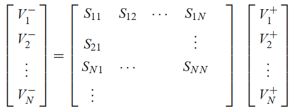
This linear relation can be expressed as a matrix that gives the $V^-$ amplitudes on each port as a function of the $V^+$ amplitudes on each port

- Each $S_{ij}$ gives the amplitude $V_i^-$ as a function of the amplitude $V_j^+$ when all other $V_k^+$, $k\neq j$, are zero.
- If the network is lossless, $S$ is unitary
- If the network is reciprocal (i.e. passive, direction-independent), $S$ is symmetric
Further study
Pozar’s chapter 4 introduces many other topics of interest:
- Impedance and Admittance matrices
- ABCD transmission matrices
- Modal analysis for discontinuities
- Excitation of waveguides with currents or apertures